.png)


ob体育app官网下载
,产品商标“YW”,是上海御微ob体育app官网下载有限公司的子公司,公司注册在陕西省西咸新区秦汉新城自贸区内。
本公司针对特殊用户的特殊需求,生产非标ob体育app官网下载,并提供最佳的解决方案,以满足客户苛刻的使用环境。ob体育app官网下载>


【2020-09-11】
【2020-09-10】

【2017-10-03】
【2017-04-01】
【2017-04-01】
【2017-04-01】
【2017-04-01】
【2017-04-01】
【2017-04-01】
【2017-04-01】
【2017-04-01】
【2017-04-01】


陕西移动端

陕西公众号

上海移动端

上海公众号


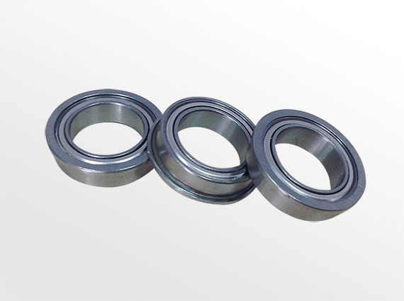
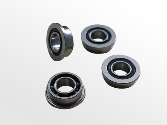
 微型法兰ob体育app官网下载